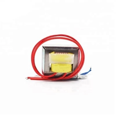
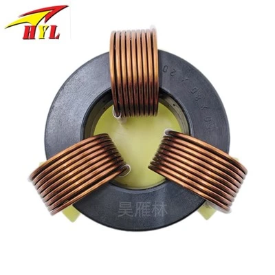
Flyback transformers generally operate in two modes:
1. Discontinuous Inductor Current Mode (DCM), also known as "complete energy conversion": All energy stored in the transformer is transferred to the output during the toff cycle.
2. Continuous Inductor Current Mode (CCM), also known as "incomplete energy conversion": A portion of the energy stored in the transformer is retained at the end of the toff cycle until the beginning of the next toff cycle. DCM and CCM have significantly different small-signal transfer functions, as shown in Figure 3. In practice, when the converter input voltage VIN or load current IL varies over a large range, both operating modes are inevitably involved. Therefore, flyback converters require stable operation in both DCM and CCM modes, which is challenging in design. Typically, we can use the critical state of DCM/CCM as a design benchmark and employ current-mode PWM control. This method effectively solves various problems associated with DCM, but... The inherent instability of the CCM (Continuous Computational Mode) circuit cannot be eliminated. The instability caused by the "right half-plane zero" of the transfer function during CCM can be addressed by adjusting the control loop gain to isolate the low-frequency band and reducing the transient response speed. DCM and CCM are very different in terms of their small-signal transfer functions. [DCM/CCM primary and secondary current waveform diagrams] In reality, when the converter input voltage VIN or load current IL varies within a large range, it inevitably spans two operating modes. Therefore, flyback converters require stable operation in both DCM and CCM, which is challenging in design. Typically, we can use the DCM/CCM critical state as a design benchmark and employ current-mode PWM control. This method effectively solves various problems during DCM, but the inherent instability of the CCM circuit cannot be eliminated. The instability caused by the "right half-plane zero" of the transfer function during CCM can be addressed by adjusting the control loop gain to isolate the low-frequency band and reducing the transient response speed. The resulting instability.
In a steady state, the change in magnetic flux increment ΔΦ during "ton" must be equal to the change during "toff," otherwise core saturation will occur.
Therefore,
ΔΦ = VIN ton / Np = Vs * toff / Ns
That is, the volts per second value per turn of the transformer primary winding must be equal to the volts per second value per turn of the secondary winding.
Comparing the current waveforms of DCM and CCM in Figure 3, we can see that: in the DCM state, during the Tr ton period, there is a higher primary peak current in the entire energy transfer waveform. This is because the primary inductance value Lp is relatively low, causing a sharp increase in Ip. The negative effect of this is increased winding losses. The switching transistor must have a high current carrying capacity to operate safely, due to the ripple current from the input filter capacitor (LOC) and the loss (LOL) of the input filter capacitor. In CCM (Continuous Current Management), the primary peak current is lower, but the switching transistor has a higher collector current in the ton state. This leads to high power consumption of the switching transistor. Simultaneously, to achieve CCM, a higher transformer primary inductance (Lp) is required. The residual energy stored in the transformer core necessitates a larger transformer size than in DCM, while other coefficients remain the same.