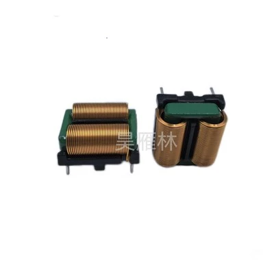
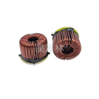
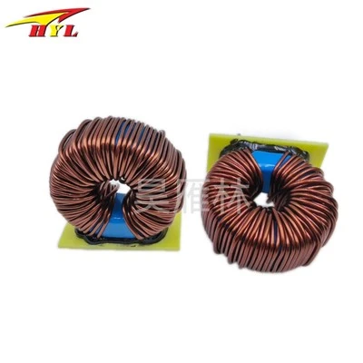
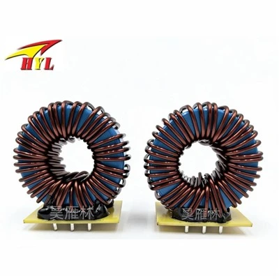
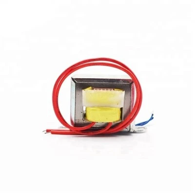
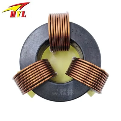
Measuring the saturation characteristics of a common-mode choke core (whole or partially) is often difficult. A simple experiment can reveal the extent to which the attenuation of a common-mode filter is affected by the reduction in inductance caused by a 60Hz cascading current. This test requires an oscilloscope and a differential mode rejection network (DMRN). First, monitor the line voltage with the oscilloscope. Input the signal to channel A of the oscilloscope as follows: set the oscilloscope's time base to 2ms/div, and then apply a trigger signal to channel A. A line current will be generated when the AC voltage reaches its peak; at this point, the degradation of filter performance is expected. Connect the input of the differential mode rejection network (DMRN) to the LISN, and match the output with a 50Ω impedance to channel B of the oscilloscope. When the common-mode choke is operating in the linear region, the increase in emissions monitored by channel B during input current fluctuations does not exceed 6-10dB. During peak line voltage, the bridge rectifier conducts forward and delivers charging current.
If the common-mode choke saturates, emissions will increase with increasing input surge. If the common-mode choke reaches strong saturation, the emission intensity is the same as without a filter, meaning it easily exceeds 40dB.
These experimental data can be interpreted using other methods. The minimum emission (when the line current is 0) represents the effect of the filter without bias current. The ratio of peak emission to minimum emission, i.e., the degradation factor, measures the impact of line current offset on the actual performance of the filter. A large degradation factor indicates that the common-mode choke core is not being used properly; a good filter's "inherent degradation factor" is approximately between 2 and 4. This is caused by two phenomena: first, the inductance reduction caused by the 60Hz charging current (as mentioned above); second, the forward and reverse conduction of the bridge rectifier. The equivalent circuit for common-mode emission consists of a voltage source with an impedance of approximately 200pF, diode impedance, and LISN common-mode impedance. When the bridge rectifier is forward biased, a voltage divider occurs between the source impedance, the 25pF diode impedance, and the LISN common-mode impedance.