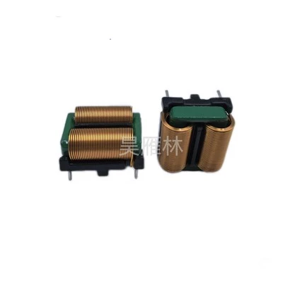
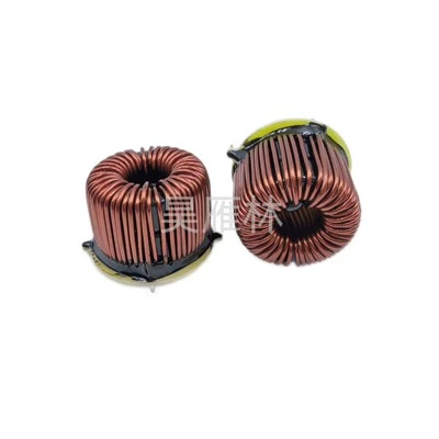
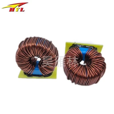
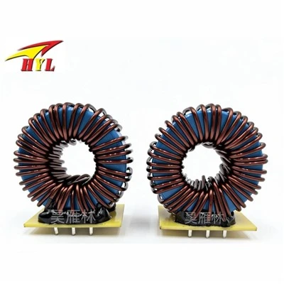
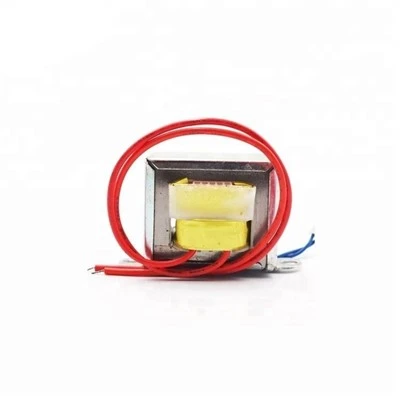
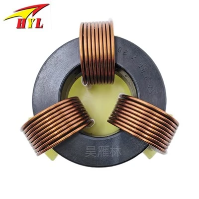
In high-frequency transformer design, leakage inductance and distributed capacitance must be minimized because high-frequency transformers in switching power supplies transmit high-frequency pulse square wave signals. During transient transmission, leakage inductance and distributed capacitance can cause surge currents, voltage spikes, and top oscillations, increasing losses. Typically, the leakage inductance of a transformer is controlled to be 1%–3% of the primary inductance.
Primary coil leakage inductance-Transformer leakage inductance is caused by incomplete magnetic flux coupling between the primary and secondary coils, between layers, and between turns.
Distributed capacitance-The capacitance formed between turns of the transformer windings, between upper and lower layers of the same winding, between different windings, and between the winding and the shielding layer is called distributed capacitance.
Primary winding-The primary winding should be placed in the innermost layer. This minimizes the wire length per turn of the primary winding, thus reducing the overall wire usage and effectively decreasing the distributed capacitance of the primary winding itself.
Secondary winding-After the primary winding is wound, 3–5 layers of insulating padding should be added before winding the secondary winding. This reduces the capacitance of the distributed capacitance between the primary and secondary windings and increases the insulation strength between them, meeting the insulation withstand voltage requirements.
Bias winding-Whether the bias winding is wound between the primary and secondary windings or on the outermost layer depends on whether the switching power supply is adjusted based on the secondary voltage or the primary voltage.