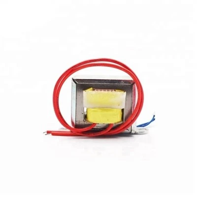
When the switching transistor Tr is turned on (ton), the primary winding of the transformer, Np, carries a current Ip, storing energy within it (E = Lp*Ip^2 / 2). Since Np and Ns have opposite polarities, diode D is reverse-biased and cut off, with no energy transferred to the load. When the switch Tr is turned off, according to Lenz's law (e = -NΔΦ/ΔT), a reverse electromotive force will be generated in the primary winding of the transformer. Diode D will then conduct forward, and current IL will flow through the load. The steady-state waveform of the flyback converter: The conduction time ton determines the amplitudes of Ip and Vce: Vce max = VIN / (1-Dmax) VIN: Input DC voltage; Dmax: Maximum duty cycle Dmax = ton / T Therefore, to obtain a low collector voltage, Dmax must be low, i.e., Dmax < 0.5. In practical applications, Dmax is usually taken as 0.4 to limit Vcemax ≦ 2.2VIN. Switching transistor Tr The collector current Ie when the primary side is on, which is also the peak primary current Ip, is: Ic = Ip = IL / n. Since IL = Io, when Io is constant, the turns ratio n determines the magnitude of Ic. The above formula is derived based on the power conservation principle, where the ampere-turns of the primary and secondary sides are equal: Np*Ip = Ns*Is. Ip can also be expressed as follows:
Ic = Ip = 2Po / (η*VIN*Dmax) η: Converter efficiency
The formula is derived as follows:
Output power: Po = LIp^2η / (2T)
Input voltage: VIN = L*di / dt Let di = Ip, and 1 / dt = f / Dmax, then:
VIN = L*Ip*f / Dmax or Lp = VIN*Dmax / (Ip*f)
Then Po can also be expressed as:
Po = η*VIN*f*Dmax*Ip^2 /(2f*Ip) = 1/2*η*VIN*Dmax*Ip
∴Ip = 2Po / (η*VIN*Dmax)
In the above formula:
VIN: Minimum DC input voltage (V)
Dmax: Maximum duty cycle
Lp: Primary inductance of the transformer (mH)
Ip: Peak primary current of the transformer (A)
f: Slewing frequency (kHz)