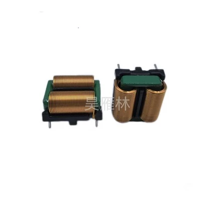
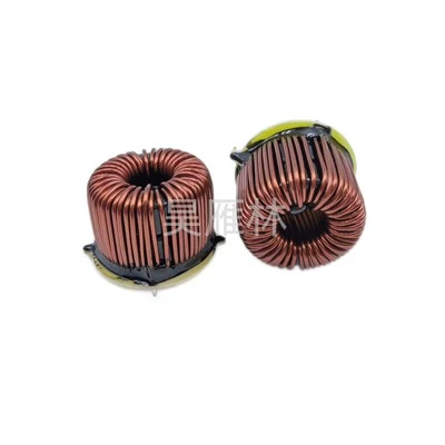
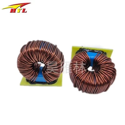
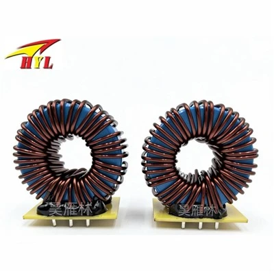
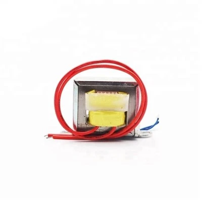
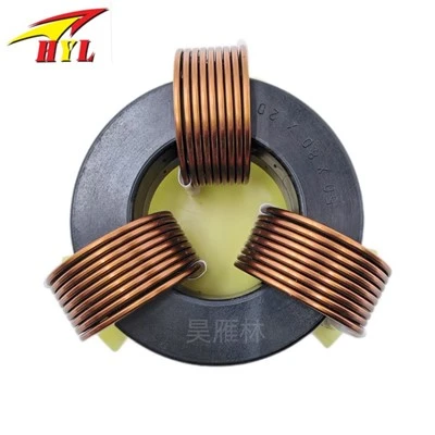
In a common-mode inductor filtering circuit, La and Lb are the common-mode inductor coils. These two coils are wound on the same iron core with the same number of turns and phase (wound in opposite directions). Thus, when normal current flows through the common-mode inductor, the current generates opposing magnetic fields in the inductor coils wound in the same phase, canceling each other out. At this time, the normal signal current is mainly affected by the coil resistance (and a small amount of damping due to leakage inductance). When common-mode current flows through the coil, due to the unidirectional nature of the common-mode current, a unidirectional magnetic field is generated within the coil, increasing the coil's inductive reactance and making it exhibit high impedance, producing a strong damping effect. This attenuates the common-mode current, achieving the filtering purpose.
This filtering circuit connects one end to the interference source and the other end to the device being interfered with. La and C1, and Lb and C2, then form two sets of low-pass filters, which can control the common-mode EMI signal on the line to a very low level. This circuit can suppress external EMI signals and attenuate EMI signals generated during the circuit's operation, effectively reducing the intensity of EMI interference.