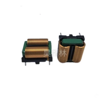
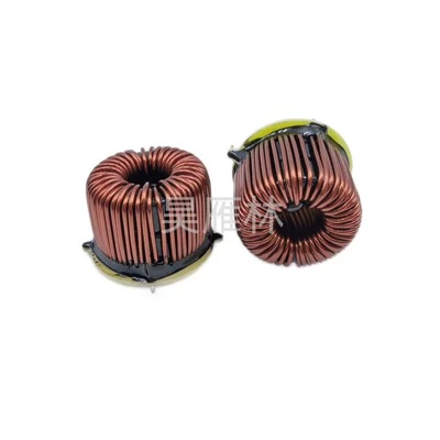
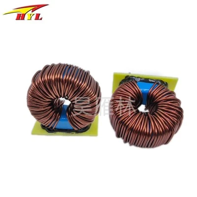
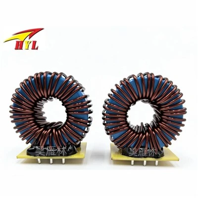
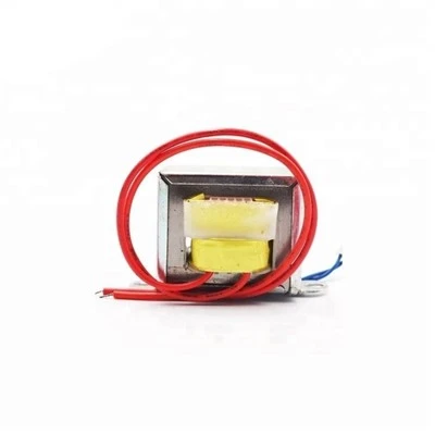
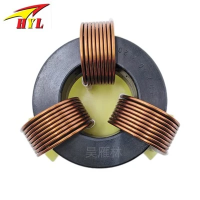
A power supply EMI noise filter is a passive low-pass filter that transmits AC power to the power source without attenuation, while significantly attenuating EMI noise transmitted with the AC power. Simultaneously, it effectively suppresses EMI noise generated by power supply equipment, preventing it from entering the AC mains and interfering with other electronic equipment. Noise filters can be classified according to their working principle into passive filters (composed of passive components such as capacitors, inductors, and resistors) and active filters (including active compensation circuits). Active EMI filters are small in size and lightweight, and can detect and suppress interference signals injected in reverse in real time. Based on frequency response characteristics, they can be classified into low-pass, high-pass, band-pass, band-stop, notch, all-pass, and comb filters, with low-pass filters being commonly used for EMI squelch filters. Based on installation methods, they can be classified into board-mounted, DIN rail-mounted, chassis-mounted, surface mount (SMT), and through-hole mounting.
Common circuit topologies for noise filters also include π-type, T-type, L-type, and their combinations to accommodate different source impedance and load impedance matching requirements.
The basic structure of a single-phase AC mains noise filter. It is a four-terminal passive network composed of lumped-parameter components. The main components used are common-mode inductors L1 and L2, differential-mode inductors L3 and L4, common-mode capacitors CY1 and CY2, and differential-mode capacitor CX. If this filter network is placed at the input of the power supply, L1 and CY1, and L2 and CY2, respectively, constitute two pairs of low-pass filters between independent ports on the AC input line. This attenuates common-mode interference noise on the AC input line, preventing it from entering the power supply equipment. The common-mode inductors are used to attenuate common-mode noise on the AC input line. L1 and L2 are typically wound with the same number of turns in the same direction on a ferrite core with a closed magnetic circuit. After being connected to the circuit, the magnetic flux generated by the AC current in the two coils cancels each other out, preventing magnetic flux saturation of the core and ensuring that the inductance values of these two coils are relatively large and remain constant in the common-mode state.