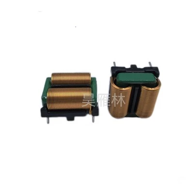
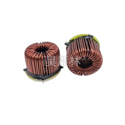
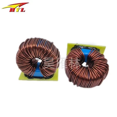
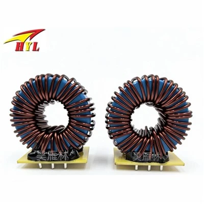
Key performance parameters for noise filters, especially EMI power filters, include insertion loss, rated voltage and current, cutoff frequency, impedance characteristics, common-mode and differential-mode rejection capability, leakage current, and operating temperature range. Insertion loss (IL) is the core indicator of filter performance, defined as the ratio of power transferred from the source to the load before and after the filter is connected. The formula is IL = 10log10(P1/P2) dB, and its value is affected by the matching degree between the source impedance (RS) and the load impedance (RL), following the "maximum mismatch principle." Rated current selection should be based on the maximum operating current of the equipment with a margin. Leakage current is defined as the current from the filter casing to either end of the AC input line under rated AC voltage, and is strictly limited in sensitive fields such as medical applications.
Taking a typical π-type EMI power filter as an example, its design method includes requirements analysis, calculation of the cutoff frequency, selection and calculation of component parameters, consideration of parasitic parameters, and simulation and iteration. First, it is necessary to determine the type of noise to be suppressed, the frequency range, and the target attenuation (VATT = measured noise value - regulatory limit). The cutoff frequency (fR) of the filter is calculated based on the target attenuation and attenuation slope. Component parameter calculations require selecting the Y capacitor (CY) capacitance according to safety specifications (such as leakage current limits), calculating the common-mode inductance (Lc) value based on the cutoff frequency and impedance, using the leakage inductance of the common-mode inductor as the differential-mode inductor or designing a separate differential-mode inductor (Ldm), and calculating the X capacitor (CX) value to suppress differential-mode noise. If necessary, a bleed resistor (R) is designed for the X capacitor. The design must consider the impact of parasitic parameters such as the equivalent series inductance (ESL) of the capacitor and the distributed capacitance of the inductor on high-frequency performance, and verification and parameter optimization are performed using circuit simulation software.